Server-room cooling controller
Automation project, 2026Summary
A server-room cooling controller designed to keep servers cool during continuous operation, with a target room temperature of 24–26 °C. Built in CODESYS, the project covers the process from defining the operating sequence to simulating and testing the controller.
- Define the operating sequence in plain language.
- Identify the input and output signals and the variables needed by the program.
- Develop the ladder logic for normal operation.
- Anticipate equipment faults and define how the controller and operator should respond.
- Design an operator HMI for monitoring equipment status and controlling the unit.
- Simulate the room and equipment, then test normal operation and fault responses.
The task
A small server room contains equipment that produces heat continuously. One cooling unit, with a circulation fan and a compressor, serves the room.
Design a control system for this cooling unit with the following requirements:
- The unit should maintain room temperature within a target range of 24–26 °C.
- An operator should be able to manually turn the unit on and off and monitor the room temperature and equipment status.
- The compressor should operate only when the fan is confirmed running.
- The compressor should remain off for at least three minutes between runs to reduce wear and starting stress.
Understanding the system
The compressor moves heat from the indoor coil to the outdoor unit, and the indoor fan moves room air across that coil. Without airflow the coil can ice up and liquid refrigerant can reach the compressor, so the compressor may only run while the fan confirms it is running.
Sequence
Normal operation
- While the unit is stopped, the fan and compressor are off.
- Start enables the unit and switches on the fan. The fan runs whenever the unit is enabled.
- The compressor runs only when cooling is needed, fan feedback is present and the restart delay has finished. Losing fan feedback stops it immediately.
- Cooling is needed from 26 °C until the room falls to 24 °C. When the unit is enabled below 26 °C, it starts with no cooling request.
- The compressor stays off for at least three minutes between runs, including after controller startup. Stop and Start do not reset the delay.
- Stop switches off the fan and compressor. A held Start button cannot restart the unit.
Faults and warnings
- Fan switched on without running feedback for 10 s: fan fault, unit stops. Covers both failure to start and loss while running.
- While the fan fault is active, Start is blocked.
- Compressor switched on without running feedback for 5 s: compressor fault, compressor stops, fan keeps running.
- High-temperature warning at 30 °C, clearing below 29 °C. Cooling continues.
- Reset works only while the unit is stopped, and a new Start is needed afterwards.
| Condition | Compressor response | Fan and unit response | Indication | How it clears |
|---|---|---|---|---|
| Fan commanded on without running feedback for 10 s | Command switches off immediately on feedback loss | Unit is disabled and fan command switches off when the fault activates | Fan fault, held until reset | Press Reset while the unit is stopped |
| Compressor commanded on without running feedback for 5 s | Command switches off when the fault activates | Unit stays enabled; fan continues running | Compressor fault, held until reset | Press Stop, then Reset |
| Room temperature reaches 30 °C | Temperature control continues | No change to operation | High-temperature warning | Clears automatically below 29 °C |
Signals and variables
| Input | Why it exists |
|---|---|
| Room temperature | Decides when cooling starts and stops. |
| Fan running | Permits the compressor; detects a fan fault. |
| Compressor running | Detects a compressor fault. |
| Output | Why it exists |
|---|---|
| Fan command | Runs the fan while the unit is enabled. |
| Compressor command | Runs the compressor when cooling is needed and its conditions are met. |
I/O list
| Tag | Description | I/O type | Signal | Address | Range | Fail-safe state |
|---|---|---|---|---|---|---|
TT-101 | Room temperature | AI | 4–20 mA | %IW0 | 0–50 °C | – |
FAN-101-FB | Fan running feedback | DI | 24 V DC | %IX0.0 | – | Off = not running |
CMP-101-FB | Compressor running feedback | DI | 24 V DC | %IX0.1 | – | Off = not running |
FAN-101-CMD | Fan run command | DO | 24 V DC | %QX0.0 | – | Off |
CMP-101-CMD | Compressor run command | DO | 24 V DC | %QX0.1 | – | Off |
Variable list
| Variable | Type | Comes from | Tag | Purpose |
|---|---|---|---|---|
rRoomTemp | REAL (°C) | Temperature sensor | TT-101 | Room temperature used for cooling demand and the high-temperature warning. |
xFanRunning | BOOL | Equipment feedback | FAN-101-FB | True when fan-running feedback is present; permits compressor operation. |
xCompRunning | BOOL | Equipment feedback | CMP-101-FB | True when compressor-running feedback is present; used for fault detection. |
xFanCmd | BOOL | Control logic | FAN-101-CMD | True while the controller commands the fan to run. |
xCompressorCmd | BOOL | Control logic | CMP-101-CMD | True while the controller commands the compressor to run. |
xStartBtn | BOOL | Operator screen | – | True while Start is pressed. |
xStopBtn | BOOL | Operator screen | – | True while Stop is pressed. |
xResetBtn | BOOL | Operator screen | – | True while Reset is pressed. |
fbStartEdge | R_TRIG | Control logic | – | Detects a new Start press, so holding Start cannot repeatedly start the unit. |
xStartPulse | BOOL | Control logic | – | One-scan signal from fbStartEdge used to set the unit-enable latch. |
xUnitEnabled | BOOL | Control logic | – | Remembers the enabled state after Start is released; clears on Stop or a fan fault. |
xCoolingRequest | BOOL | Control logic | – | Requests cooling at ≥26 °C; clears at ≤24 °C or when disabled; holds its state between thresholds. |
fbCompOffTimer | TON | Control logic | – | Times how long the compressor command has been off; resets when the command turns on. |
xCompOffDone | BOOL | Control logic | – | True when the minimum off-time has elapsed, allowing a compressor start. |
fbFanTimer | TON | Control logic | – | Times missing fan-running feedback while the fan is commanded on. |
xFanTimeout | BOOL | Control logic | – | True after 10 seconds of fan command without running feedback. |
xFanFault | BOOL | Control logic | – | Stops the unit after a fan timeout; remains active until reset while stopped. |
fbCompTimer | TON | Control logic | – | Times missing compressor-running feedback while the compressor is commanded on. |
xCompTimeout | BOOL | Control logic | – | True after 5 seconds of compressor command without running feedback. |
xCompFault | BOOL | Control logic | – | Blocks the compressor after a timeout; remains active until reset while stopped. |
xHighTempWarn | BOOL | Control logic | – | High-temperature warning: activates at ≥30 °C and clears below 29 °C without stopping cooling. |
rCoolOnTemp | REAL, 26.0 | Fixed setting | – | Room temperature at or above which cooling is requested. |
rCoolOffTemp | REAL, 24.0 | Fixed setting | – | Room temperature at or below which the cooling request clears. |
timMinOffTime | TIME, 3 min | Fixed setting | – | Minimum time the compressor command must stay off before another start, also applied after startup. |
timFanFaultTime | TIME, 10 s | Fixed setting | – | Time allowed for missing running feedback while the fan is commanded on. |
timCompFaultTime | TIME, 5 s | Fixed setting | – | Time allowed for missing running feedback while the compressor is commanded on. |
rHighTempOn | REAL, 30.0 | Fixed setting | – | Room temperature at or above which the high-temperature warning activates. |
rHighTempOff | REAL, 29.0 | Fixed setting | – | The high-temperature warning clears below this room temperature. |
GVL_IO; all others local to PRG_Control.Control logic
Normal operation (without faults)
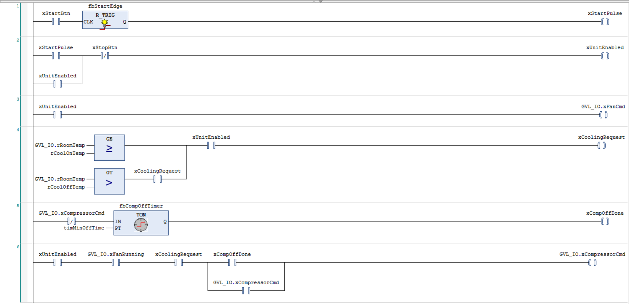
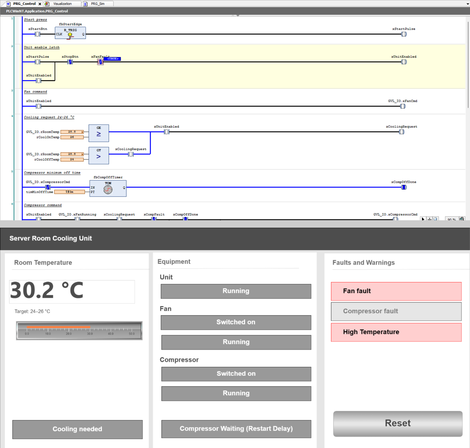
Six rungs cover normal operation: Start and Stop, the fan, the 24–26 °C cooling request, the restart delay and the compressor.
With faults and a high-temperature warning
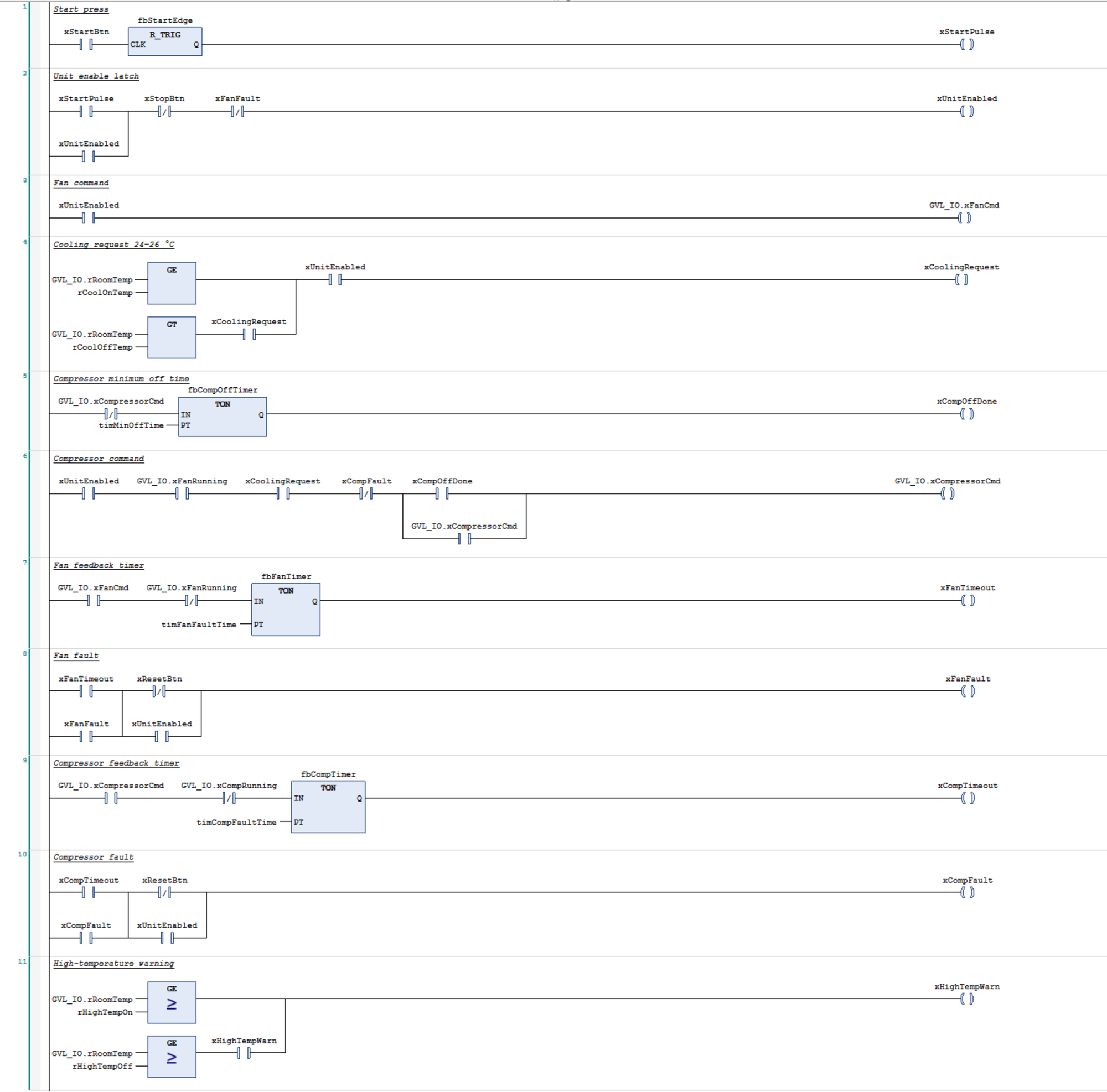
Five rungs add a feedback timer and fault latch for the fan and the compressor, plus the high-temperature warning. Two normal rungs change:
- Rung 2: the fan fault breaks the unit-enable latch and blocks Start.
- Rung 6: the compressor fault blocks the compressor; the fan keeps running.
Simulating the process
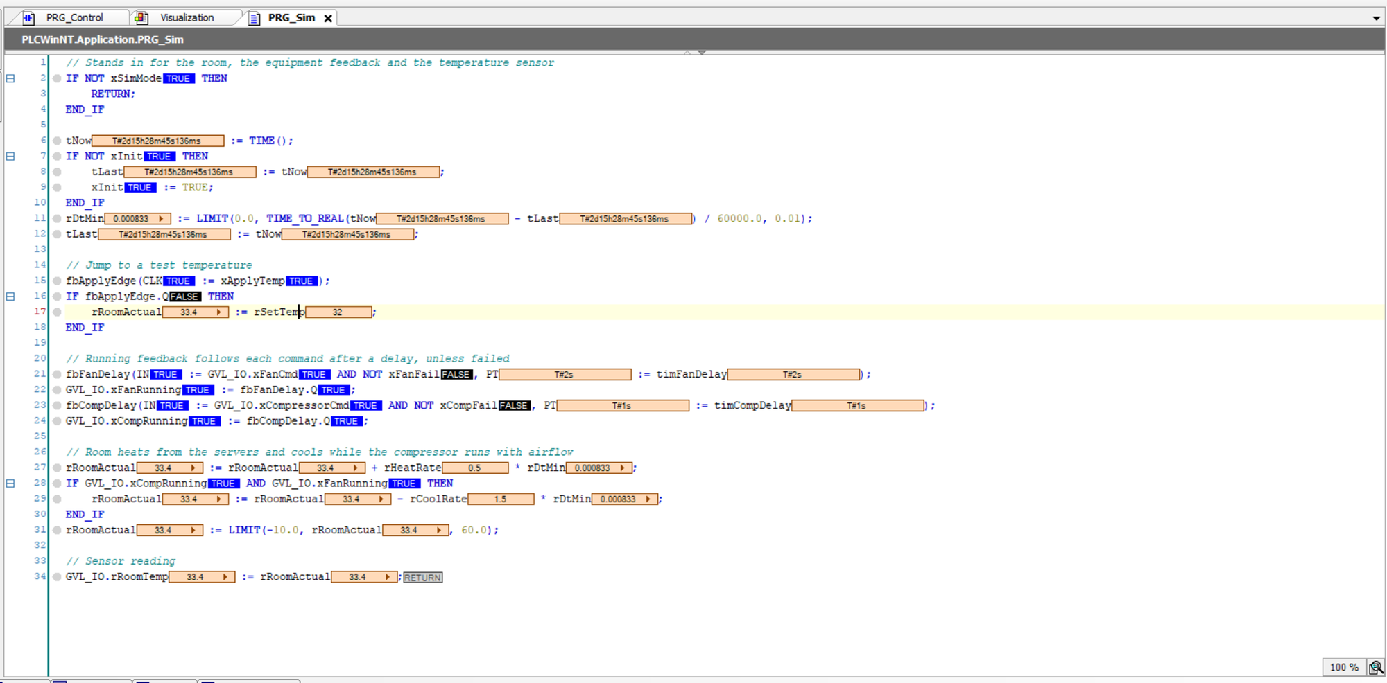
With no physical equipment, a Structured Text program, PRG_Sim, stands in for the room and equipment. It heats the room at a constant rate, cools it while the compressor and fan run, returns running feedback shortly after each command, and has switches to fail the fan or compressor and to set the room temperature for tests.
PRG_Sim running online.Operator screen
HMI design decisions
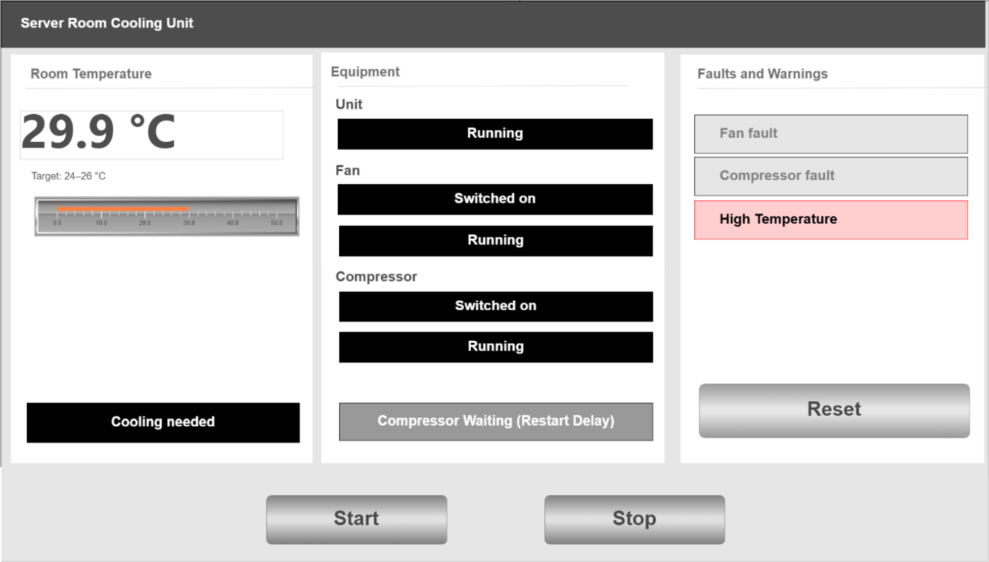
- Read left to right: room, equipment, then faults.
- Room temperature is the largest element, with the target band beside it.
- Related items grouped in titled panels; each label sits next to its indicator.
- Command and running feedback shown separately, so a mismatch is visible before the fault trips.
- Grey for off, dark for on; colour reserved for faults and the warning.
- Box text names the state it shows, so lit reads as yes.
- Reset beside the faults it clears; Start and Stop apart at the bottom.
- Momentary buttons; the logic handles a held Start.
Testing
Eleven of 22 recorded checks, run in CODESYS simulation. Boundary tests held the room temperature fixed. The three-minute delay was tested at full length; later checks used 20 s to save time.
| Test | Condition and action | Expected result | Observed result | Result |
|---|---|---|---|---|
| 1 | Press Start with the room at 25 °C | Fan command turns on; running feedback follows after about 2 s; no cooling request | Fan command on; feedback present at 2.8 s; cooling request off | Pass |
| 2 | Press Start at 27 °C and read the outputs before fan feedback arrives | Compressor command stays off while fan feedback is absent | Cooling requested; fan feedback absent; compressor command off | Pass |
| 3 | While cooling, set 24.1 °C, then 24.0 °C. After the off-time, set 25.9 °C, then 26.0 °C | Compressor stays on at 24.1 °C, stops at 24.0 °C, stays off at 25.9 °C and starts at 26.0 °C | All four switching checks matched the expected result; fan kept running | Pass |
| 4 | Compressor stops, cooling needed again straight away | Compressor waits three minutes, then starts | Still off at 2 min 54 s; started at 3 min | Pass |
| 5 | Stop while cooling, Start again after 1 minute | Compressor waits the remaining 2 minutes | Started 3 min after the stop | Pass |
| 6 | Start and Stop pressed together | Unit stays stopped | Unit stayed stopped | Pass |
| 7 | Suppress fan feedback, press Start, then try Start while faulted. Reset and start again with feedback still suppressed | Fan fault after 10 s; both commands off; Start blocked while faulted; fault returns after a reset and restart | Unit disabled and both commands off; Start was blocked; fault returned after 10 s on retry | Pass |
| 8 | Suppress fan feedback while cooling | Compressor command switches off immediately; fan fault disables the unit after 10 s | Compressor stopped immediately; fan fault stopped the unit after 10 s; no compressor fault | Pass |
| 9 | Suppress compressor feedback while running. Try Reset, then press Stop and Reset | Compressor fault after 5 s; fan keeps running; Reset is ineffective until the unit is stopped | Compressor command off after the fault; fan kept running; fault cleared only after Stop and Reset | Pass |
| 10 | Set room temperature to 29.9, 30.0, 29.0 and 28.9 °C in order | Warning activates at 30.0 °C, remains at 29.0 °C and clears at 28.9 °C; cooling continues | No warning at 29.9 °C; warning active at 30.0 and 29.0 °C; cleared at 28.9 °C without stopping cooling | Pass |
| 11 | Perform a controller warm reset while the unit is running | Unit returns stopped, with both commands off and no active faults | Unit returned stopped with no faults; minimum off-time setting was three minutes | Pass |
Limitations
- This is a simulation. It is not a commissioned or safety-validated installation, and no standards compliance is claimed.
- Temperatures, timings and signal types were selected for this project and have not been validated against a specific installation or manufacturer's data.
- There is no standby cooling unit to take over if the unit fails.
Reflection and next steps
Breaking the task down into an operating sequence helped me understand what the program needed before writing the ladder logic. It separated the temperature decision from the conditions that allow the compressor to run, such as fan confirmation and the minimum off-time.
Considering faults alongside that sequence helped me identify what feedback the controller needed. A run command alone could not show whether the equipment had started, which is why the fault-handling stage needed running feedback from both the fan and the compressor.
Building and testing normal operation first made the later changes easier to follow. I could then check how each fault affected the existing sequence, including what stopped, what continued running and what the operator needed to do before restarting.
Next steps
- Add temperature-sensor fault detection and define an appropriate cooling response for loss of the reading.
- Add analogue-input scaling to convert a raw 4–20 mA reading into room temperature.
- Add a standby cooling unit and changeover logic so cooling can continue if the active unit fails.